Skip to content
Cognitive neuroscienceThe Neural Mind
Contents and reading path

Chapter 2

Sensation, Perception and Action

  1. 2.1How does the world become an experience?
  2. 2.2From stimulation to nerve signals
  3. 2.3Vision and visual perception
  4. 2.4Hearing and the direction of sound
  5. 2.5When the senses work together
  6. 2.6The cup in a noisy café
  7. 2.7How does a movement take shape?
  8. 2.8Prediction, feedback and learning
  9. LabThe visual lab

Perception and motor learning – in preparation

Reading path
Coming chapters (planned content)
  1. 1. Introduction to Cognitive Neuroscience
  2. 3. Attention
  3. 4. Memory and Learning
  4. 5. Language
  5. 6. Thinking and Executive Functions
  6. 7. Decision-Making
  7. 8. Emotion and Motivation
  8. 9. Social Cognition
  9. 10. Metacognition and Consciousness

Cognitive neuroscience

The Neural Mind

An Interactive Introduction to Cognitive Neuroscience

Explore how we perceive the world and act within it, connecting everyday experience with the workings of the brain. Read at your own pace, explore the illustrations and try optional experiments. The text also stands on its own without the exercises.

Welcome to a first version of The Neural Mind. Chapter 2 has eight sections, with the fullest treatment of vision and introductory material on hearing, multisensory perception and movement. The visual lab is open for exploration. Additional senses, other chapters and deeper treatments are in development.

Reading path

The reading path offers guidance. All content remains open regardless of your choice.

Chapter 2 · Section 1

How does the world become an experience?

You see a cup, hear a voice and feel the surface of the table. How can physical events become a world that can be recognised and acted in?
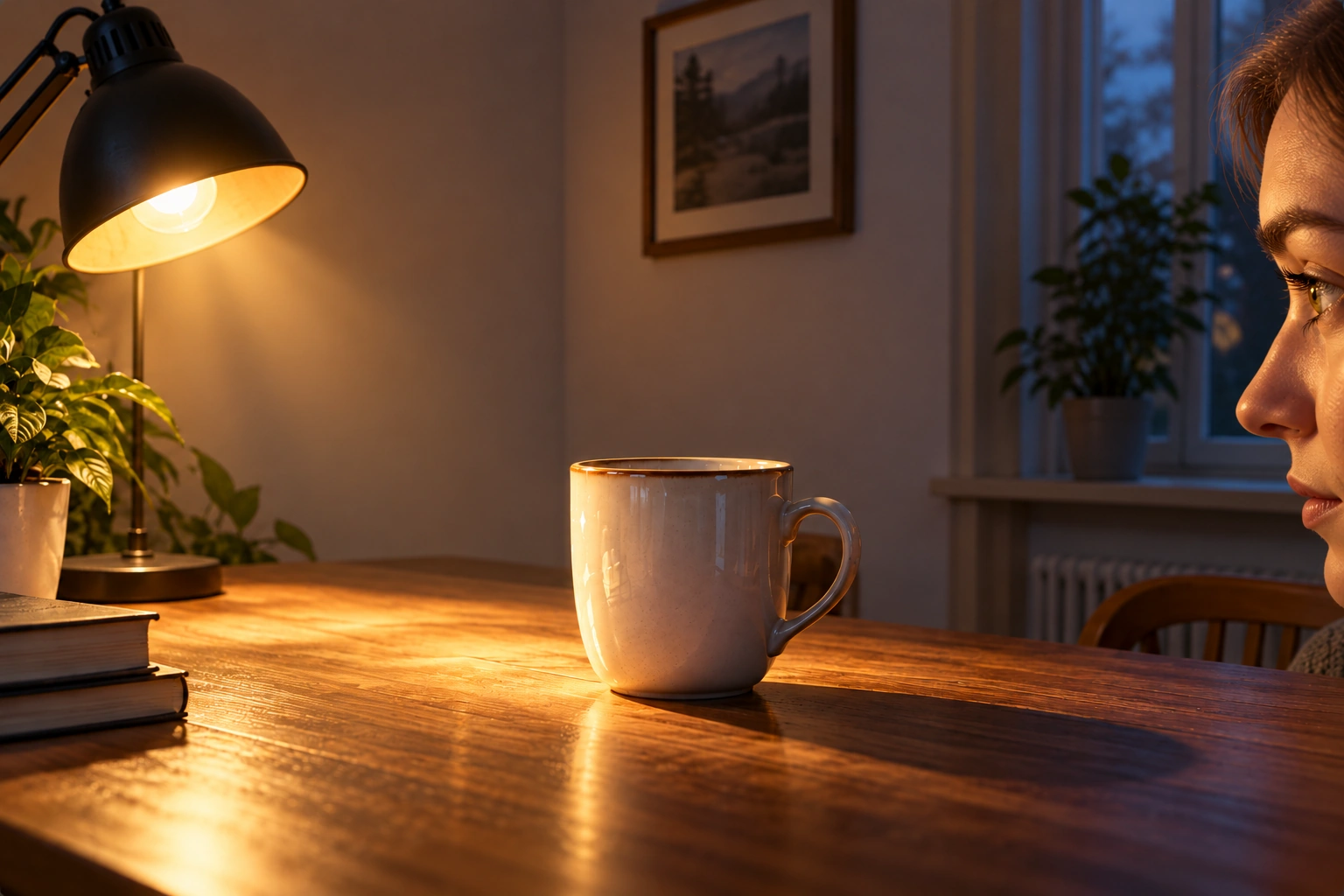
A lamp on the left illuminates a ceramic cup on a wooden table. On the right, a person looks at the cup.From light source to eyeThree selected light routes lead from the lamp via the cup, via the wall, or via the table and wall to the eye. No arrows leave the eye. Numbers identify the light source, cup, wall, table and eye in the legend below.
  1. 1Light source
  2. 2Illuminated cup surface
  3. 3Wall
  4. 4Table
  5. 5The eye receives light
Figure 2.1. From light source to eye. The lamp illuminates the cup, wall and table. Their surfaces reflect light in several directions, and some reaches the eye. Light can also be reflected between surfaces before reaching us, as along the route via the table and wall. The arrows help you follow a few of these routes.AI-generated scene with schematic light paths. Dashed line: via table and wall.

Most of what we see is reflected light

A lamp emits light. We see the cup, table and wall because they reflect light that reaches them. This is how we see most everyday objects: light from the Sun or a lamp reaches their surfaces, and some of the reflected light reaches our eyes.

Light can be described in terms of photons – small packets of energy. When light meets a material, some photons are absorbed: their energy is transferred to the material and can contribute to warming it. Others are reflected and may reach an eye or another surface. Saying that light “bounces” describes its change of direction at a surface.

Reflection

Incoming lightReflected light
ReflectionThree separate examples: solid arrows reach different points on a textured ceramic surface; dashed arrows leave those points in different directions. No arrow branches.

The same matte ceramic

Reflection: a matte surface scatters reflected light in many directions. This lets us see the surface from different positions.

Absorption

Incoming lightAbsorbed light
AbsorptionTwo separate incoming arrows extend a short way into the same ceramic material and end at stop bars with energy-transfer symbols. No light leaves the underside.

The same matte ceramic · Energy to the material

Absorption: the photon's energy is transferred to the material. The absorbed photon does not continue towards the eye.

Figure 2.1b. When light meets a surface. An opaque material is shown here. Some light can also pass through transparent materials. The arrows show selected examples, not measured proportions.Original schematic illustration. Symbols inside the material indicate energy transfer.

Light and colour in the image

Imagine standing in the room and pointing a measuring instrument at the cup. The instrument separates light arriving from the surface by wavelength. Its curve shows how much light reaches it across different parts of the visible spectrum.

Here we simulate such a measurement using the image’s colour values. The curve is one possible, simplified example — not a measurement of the room. The same image colour can correspond to several different spectra.

Point or tap in the image. Drag the probe’s round handle; swipe elsewhere in the image to scroll the page. With the handle focused, arrow keys move the probe. Adjust the wavelength slider. When you leave the image, the last sample stays selected.

Illustrated lamp, cup, table, wall and eye with a freely movable spectrum probe.Illustrated lamp, cup, table, wall and eye with a freely movable spectrum probe.

Loading image colour values …

The scale is the same throughout the image. 100% is the model’s reference level for digital white.

Figure 2.1c. Simulated light spectrum. The curve shows a simulated light spectrum on a fixed, relative scale. It does not show the surface’s reflectance.Illustrated scene with a simulated meter and schematic graph.

Continue to colour vision and colour constancy.

Arriving light and surface reflectance

A spectroradiometer measures light reaching the instrument, resolved by wavelength. The free spectrum here shows relative simulated received light, not reflectance.

A spectrophotometer determines spectral reflectance using controlled illumination and a reference. Reflectance is the fraction of incoming light reflected by the surface at each wavelength. In the surface model these fractions are authored curves, not measurements of the image.

Spectroradiometer · CIE: reflectance · Spectrophotometer

The lamp and the surface shape the light together

Daylight and lamplight contain different amounts of light at different wavelengths. This distribution is called the light source’s spectral distribution. When light meets the cup, some is absorbed and the rest is reflected. The fraction reflected at each wavelength depends on the surface.

Changing the light source can therefore change the light from the cup even though the cup itself stays the same. If the source has almost no light at certain wavelengths, the surface cannot reflect much light at those wavelengths, even if its reflectance there is high.

1. Incoming light
Incoming lightBroad and even, Ceramic cup. At each wavelength: reflected light = incoming light × reflectance / 100. The source profiles and surface curves are authored examples, not measurements of daylight, lamps or the pictured objects. The model represents a matte, opaque, non-fluorescent surface and keeps viewing angle and light scattering unchanged. The scales are fixed; the examples do not have equal total light energy.Relative level (%)0255075100380460540620700Wavelength (nm)
2. Surface reflectance
Surface reflectanceBroad and even, Ceramic cup. At each wavelength: reflected light = incoming light × reflectance / 100. The source profiles and surface curves are authored examples, not measurements of daylight, lamps or the pictured objects. The model represents a matte, opaque, non-fluorescent surface and keeps viewing angle and light scattering unchanged. The scales are fixed; the examples do not have equal total light energy.Surface reflectance (%)0255075100380460540620700Wavelength (nm)
3. Reflected light
Reflected lightBroad and even, Ceramic cup. At each wavelength: reflected light = incoming light × reflectance / 100. The source profiles and surface curves are authored examples, not measurements of daylight, lamps or the pictured objects. The model represents a matte, opaque, non-fluorescent surface and keeps viewing angle and light scattering unchanged. The scales are fixed; the examples do not have equal total light energy.Relative level (%)0255075100380460540620700Wavelength (nm)

At each wavelength: reflected light = incoming light × reflectance / 100.

The source profiles and surface curves are authored examples, not measurements of daylight, lamps or the pictured objects. The model represents a matte, opaque, non-fluorescent surface and keeps viewing angle and light scattering unchanged. The scales are fixed; the examples do not have equal total light energy.

A surface does not tell the whole story — continue to colour constancy

Materials absorb and reflect different amounts at different wavelengths. Light from the cup therefore carries information about both the illumination and the cup's surface. This will matter when we explore colour vision and colour constancy.

Authoritative background: NASA: Wave Behaviors · NASA: Interactions Between Light and Matter · OpenStax: The Law of Reflection

A cup stands on the table in front of you. You perceive its shape, colour and distance almost without effort. But what reaches the eye is light reflected from the cup and its surroundings. For you to recognise the cup, the nervous system must process the pattern of light. The information becomes useful when you choose the cup and reach for it.

Continue reading the section →